
Brushed DC Motors
Define supply voltage, speed at load, torque and operating cycle for your equipment.
Explore motor typeBRUSHED · BRUSHLESS · CORELESS
Define the voltage, operating speed, load torque and installation envelope. Start with the application, then review the motor configuration and sample-validation plan.
Start an engineering enquiry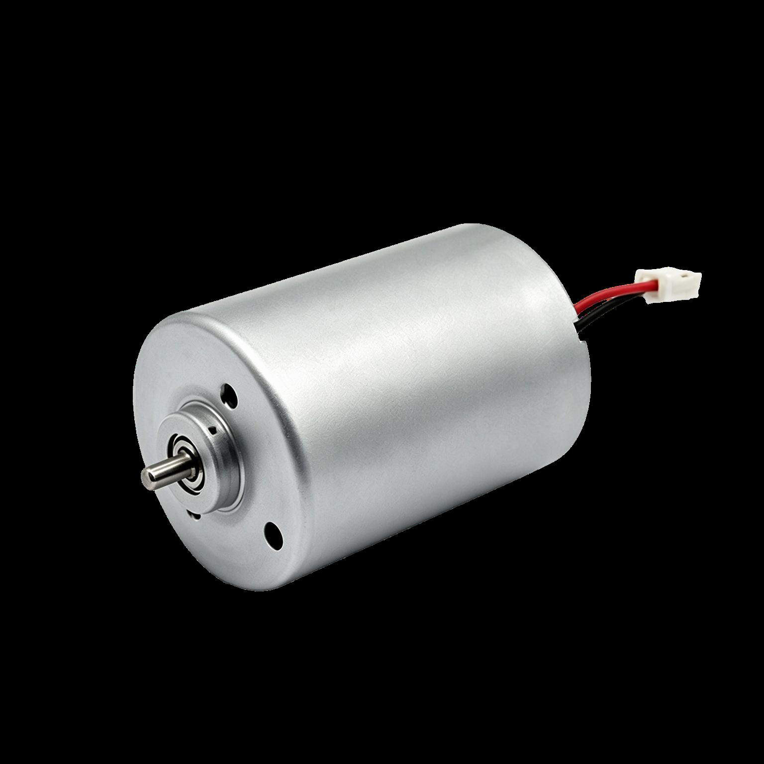
Supplied BLDC motor reference image · pending model confirmation.
Filters search published, verified motor data. If your working point is not listed, request an engineering review.
PRODUCT PLATFORMS
Define supply voltage, speed at load, torque and operating cycle for your equipment.
Explore motor typeReview the motor, driver, feedback and control interfaces as one integrated requirement.
Explore motor typeExplore coreless construction with the commutation type, load and mechanical envelope clearly specified.
Explore motor typeBrushed and brushless describe commutation. Coreless describes construction; the actual motor record identifies both.
ENGINEERING ROUTE
Define the movement, operating point and integration limits.
Review the motor platform, interfaces and control requirements.
Agree the configuration and prepare for equipment evaluation.
Check performance and integration under the agreed conditions.
Confirm the specification, documentation and supply requirements.
ENGINEERING EVIDENCE
Keep the configuration, document revision and measurement conditions connected.
Speed, torque, current and the test conditions that define the working point.
Motor envelope, shaft geometry and mounting interfaces for integration.
Connections, driver requirements and feedback for the actual configuration.
A clear link between the motor configuration and its applicable files.
APPLICATION FIRST
APPLICATION GUIDE
An engineering planning guide for defining the motorized function, interfaces and device-level validation requirements.
Review requirements ↗APPLICATION GUIDE
Plan the movement, operating sequence, package constraints and electrical interfaces for a laboratory equipment motor review.
Review requirements ↗APPLICATION GUIDE
Organize load, duty cycle, mounting and control requirements before selecting a motor configuration for automation equipment.
Review requirements ↗APPLICATION GUIDE
Define the operating task, package size, available supply and evaluation conditions for a compact equipment motor review.
Review requirements ↗OEM CUSTOMIZATION
Voltage and performance are only part of the review. Include the shaft, mounting, wiring and control requirements that make the motor fit your equipment.
Review customization options ↗Customization scope and availability are confirmed for the individual project.
LET’S REVIEW YOUR APPLICATION
Send your voltage, speed, load torque, mechanical envelope and application details.